Use a nicer approximation for anti-aliasing. #1822
Conversation
 kvark
left a comment
kvark
left a comment
There was a problem hiding this comment.
Looks fine to me. Might be worth putting some logic into shared?
|
Looks good to me, once reftests are updated. |
|
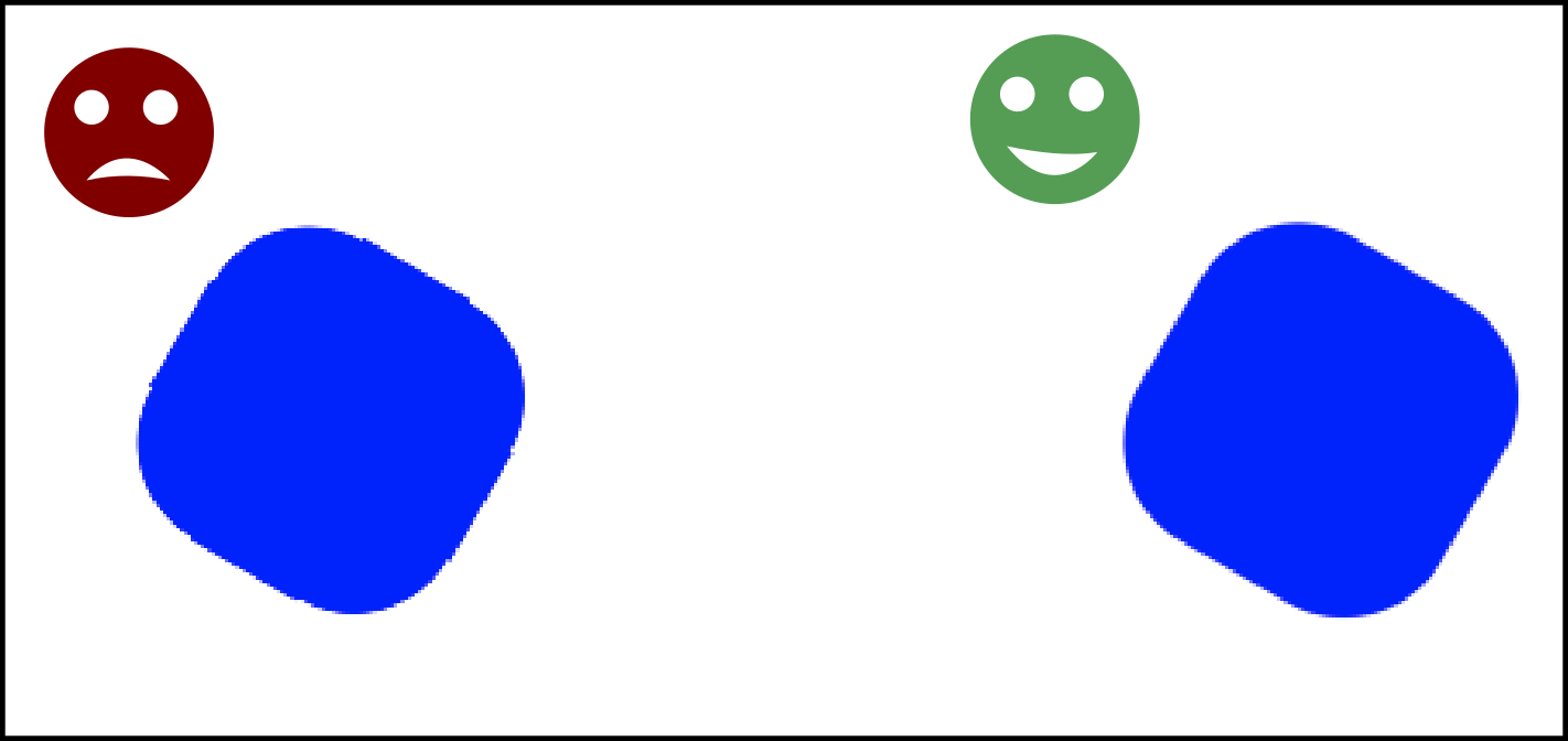
Actually I am going to have to re-do this one as well as #1791. I spent today revisiting the maths behind all of this and I found out that my fix in #1791 was not correct: I introduced an arbitrary bias that was compensating for another roughly equivalent bias, but my original assumption about the cause of the original bias was incorrect. The real cause for the ugliness in #1750Here we'll assume that the css to device transform is just a scaling transformation (showing that the simple case is wrong is enough to show that the rest is). Error in the arithmeticThen we do something a bit odd, the simplified code is: The above shifts the the inner ellipse towards the exterior of the corner, which leads to the most noticeable artefact shown in #1750 (in my opinion), where the inner part of the rounded border doesn't line up with the edges of the rectangle. It would make more sense to do: glitch due to stretched aa range(edit: remvoed some of the stuff here, better explained a few comments below). This means that instead of using The reason why a lot of people are usually widening the aa range is because it looks better as long as you don't have a junction between anti-aliased and non-antialiased edges. So that's typically good for distance field text which is most of literature about this kind of shader math online. |
|
I updated the PR to fix our aa code with more grounded math (and no more hacky bias to correct the bugs). another thing that came up while fixing this is that there were places where we would compute the aa only on a half pixel in the exterior of the shape like this: alpha = smoothstep(0.0, 0.5*length(fwidth(pos)), signed_distance)Which is incorrect, we should instead smooth half a pixel in and half a pixel out like this: float aa_range = 0.5 * length(fwidth(pos)); // we actually want 0.4 instead of 0.5 for other reasons.
alpha = smoothstep(-aa_range, aa_range, signed_distance) |
|
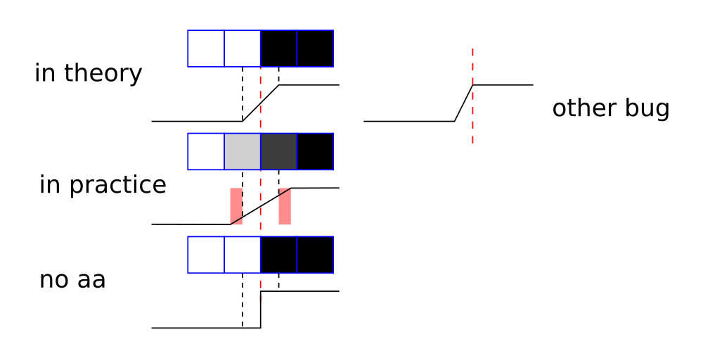
@nical it's not easy to catch up with your thought progress, but one thing would help: what is the difference (on the picture) between "in theory" and "in practice"? |
|
@kvark I am talking a lot about a particular artifact so a good start is to look at the this image and focus on the artifact that is visible at the junction between the corver and the straight edges. I made another drawing which better shows that particular bug:
What this shows is a function where y represents the alpha (white is totally outside and black totally inside), and x a signed distance to a border. In theory we want a 1 device pixel wide aa range that goes from 0.5px inside the curve to 0.5px outside the curve. So that was one of the bugs and it is fixed by using 0.4 as the coeffecient to compensate for the Another bug was when we'd do There was a few other bugs in some computations that were just wrong, it's hard to represent them graphically because the computation didn't quite make sense. Some of those in particular were the ones that made the curve look offset towards the exterior of the corner by half a pixel, which I originally misinterpreted by a pixel snapping related thing but in fact was not. |
|
@nical thanks for explanation!
Why use |
I think that there is two sides to this question. The whole aa approximation is based on the evaluating a single distance between the pixel and the shape so the math isn't separable in x and y unless we reinvent it differently. As to why using fwidth instead of, say, the average of abs(dFdx) and abs(dFdy), I don't know for sure. This is a very common technique so there is certainly a reason, perhaps it is faster that way. Another way could be to just pass the css to device pixel ratio to the shader, but that would not work as well if a perspective transformation is applied. |
|
@nical here is what I'd like to see us doing:
pseudo-code: //calculate vector to the edge for XY
// Z=+1 for outside and Z=-1 for inside
vec3 edge_vec_inside = <>;
vec2 ddx = dFdx(local_pos);
vec2 ddy = dFdy(local_pos);
// vector to the closest edge in pixel space
vec2 pixel_edge_vec = vec2(dot(edge_vec_inside.xy, ddx) / dot(ddx, dd), dot(edge_vec_inside.xy, ddy), dot(ddy, ddy));
// pixel distance of 0.0 gives us alpha 0.5, distance of 0.5 gives us alpha 0.0 for the outside part, etc
float alpha = clamp(0.5 - edge_vec_inside.z * length(pixel_edge_vec), 0.0, 1.0); |
|
I don't think that's worth it. I'd rather take the common approach since it's well documented online, easier to understand (IMO), cheaper and should the give the same results in the vast majority of cases (no complicated transforms). |
If it's well documented online, why do we struggle with it? Could you point me to that documentation explaining how the approximation was derived from a more precise AA model? |
|
There was two main sources of struggle:
My biggest struggle was that I took it for granted that the math was right and looked for causes of the artefacts where they were not (my initial theory about pixel snapping), it's only after I looked at other implementations and spent some time simplifying the code that I found out it was incorrect (thanks to your suggestion to simplify the code btw!). |
webrender/res/cs_clip_border.glsl
Outdated
| // Get AA widths based on zoom / scale etc. | ||
| vec2 fw = fwidth(local_pos); | ||
| float afwidth = length(fw); | ||
| float aa_range = 0.4 * length(fwidth(local_pos)); |
There was a problem hiding this comment.
can we have 0.4 as a constant defined somewhere with a proper name + comments?
webrender/res/cs_clip_rectangle.glsl
Outdated
| // See comment in ps_border_corner about the choice of constants. | ||
| float aa_range = 0.4 * length(fwidth(pos)); | ||
|
|
||
| return 1.0 - smoothstep(-aa_range, aa_range, current_distance); |
There was a problem hiding this comment.
would be great to share these 2 lines between shaders
|
Also, would you want to start a try push for Gecko? |
|
|
||
| // Get the groove/ridge mix factor. | ||
| color_mix_factor = smoothstep(-aa_range, aa_range, -d2); | ||
| color_mix_factor = distance_aa(aa_range, d2); |
There was a problem hiding this comment.
shouldn't this be 1.0 - distance_aa(aa_range, -d2) instead?
| // reference line, and then apply AA along the edge. | ||
| float ld = distance_to_line(vColorEdgeLine.xy, vColorEdgeLine.zw, local_pos); | ||
| float m = smoothstep(-aa_range, aa_range, ld); | ||
| float m = distance_aa(aa_range, -ld); |
There was a problem hiding this comment.
shouldn't this be 1.0 - distance_aa(aa_range, ld)?
There was a problem hiding this comment.
At a certain point my brain decided that it was equivalent, but now I am very tired and counting on the test run (and/or a good night of sleep) to help coming up with a more definitive answer to this question.
(edit:) I reactivated my poor brain and I am pretty sure it's the same thing.
There was a problem hiding this comment.
Actually, I think you are correct here. Will see the try push and merge if it's ok.
|
Looks like a reasonable number of unexpected fails that will need to be investigated :( |
|
All of the try failures have a maximum difference of 2 which is symptomatic of changing anything related to anti-aliasing. Usually when we run into those we just add fuzziness to the tests and move on. That said they are all in places where we seem to be drawing axis-aligned rectangles (I am surprised that there's any aa happening in that scenario). It could be because the constant factor (0.4 in this PR), should be 0.5/sqrt(2) = 0.35355. I chose 0.4 instead because of how smoothstep barely varies towards the endpoints (and is steeper in the middle) and with a result snapped to 256 shades of alpha I thought the aa would never leak out of the [-0.5, 0.5] pixel range. |
|
@nical so you think we should proceed with an assumption that you'll change the tests expectations right upon Gecko's WR update? |
|
@nical Cool, if we're happy to update the reftests in Gecko with fuzziness, that's great. My main concern at this point is that we have several tests in Servo / WPT that rely on pixel-perfect results when axis-aligned (i.e. no AA). I will run this PR through WPT today and report back the results! |
|
Talking to @nical in IRC, we basically need to either (a) make the AA code pixel-perfect for axis-aligned rects, or (b) use a specific shader / mode when we know the rect is axis-aligned. |
|
I'll first try with 0.35355 instead of 0.4 (and if it doesn't look as good try the same with a linear interpolation instead of smoothstep, or use the more principled constant for straight lines and 0.4 for ellipses). If the failure were in curvy things i'd just fuzz the tests without hesitation but with straight lines I'm worried we're going to end up fuzzing a lot of tests which is no fun. |
|
@nical @kvark Good news! Servo WPT results are: The first one is probably related to #1776, and the second one is probably something else. So from Servo's perspective, this PR is fine to merge. This is the Gecko try run with your constant change: https://hg.mozilla.org/try/rev/3152d4985b707a6dd3419552c4762cb77c3e4d59 I'll leave it up to @nical to decide what we need to do in regards to the Gecko failures, but r=me if we decide to update gecko fuzziness in those tests. |
|
The new gecko run is encouraging: one unexpected failure for two unexpected passes (means we fixed two tests that were not passing before). |
|
I updated the PR with reference images etc. This should be good to land, at last. There are a few places where I would have liked the aa to be a bit smoother, but at this point I think that it is best to first land this since it fixes a number of bugs, and later come back to do some polishing. For the record, some possible avenues to polish this:
|
|
@nical I think you've been tortured enough, and we know the truth now :) |
|
📌 Commit 8c429be has been approved by |
|
@staktrace heads up there are a few reftest fuzziness values to change when landing this in gecko. I'll make a patch on monday to insert in the next wr update. |
Use a nicer approximation for anti-aliasing.

Since changing `k*length(fwdith(pos))` to use `0.7` instead of `0.5` greatly improved the visual quality of the corner borders in #1791, I am following up with the same change in the other places where we use distance to edges for the anti-aliasing.

In the process of doing that I had to fix the cs_clip_rectangle shader which had two problems:
 - the aa step was added to the distance which makes no sense (the distance is in CSS pixels while the aa step can be seen as a factor of the CSS to device pixel ratio) and was the reason reftests/transforms/rotated-clip.yaml looks bad.
 - `smoothstep(0.0, afwidth, 1.0 - current_distance);` doesn't make much sense (to me) either, we want to invert the result of the smoothstep rather than what we pass to it.

<!-- Reviewable:start -->
---
This change is [<img src="https://reviewable.io/review_button.svg" height="34" align="absmiddle" alt="Reviewable"/>](https://reviewable.io/reviews/servo/webrender/1822)
<!-- Reviewable:end -->
|
☀️ Test successful - status-appveyor, status-travis |
Since changing
k*length(fwdith(pos))to use0.7instead of0.5greatly improved the visual quality of the corner borders in #1791, I am following up with the same change in the other places where we use distance to edges for the anti-aliasing.In the process of doing that I had to fix the cs_clip_rectangle shader which had two problems:
smoothstep(0.0, afwidth, 1.0 - current_distance);doesn't make much sense (to me) either, we want to invert the result of the smoothstep rather than what we pass to it.This change is